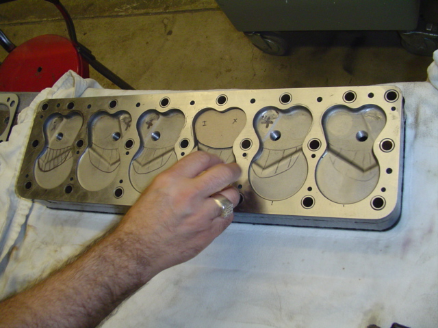
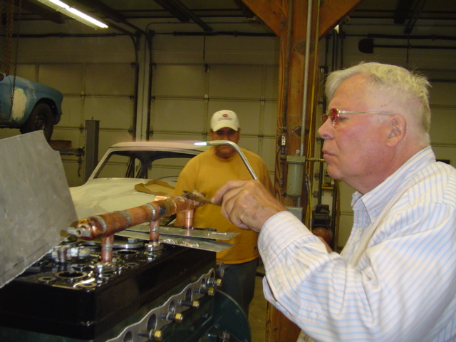
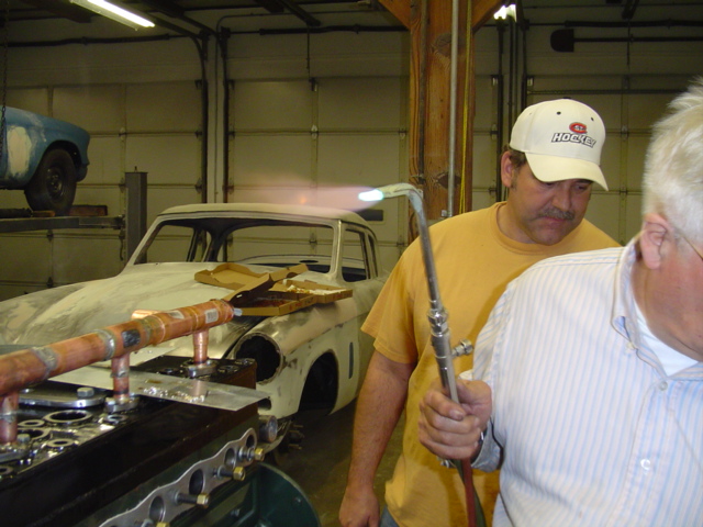
In the meantime, we still have to finish the cooling system to be ready in time for the trip to the Dyno next week! Here Mike S. and Joe start fitting the water inlets. Yes, that's right. Greg designed reverse flow cooling into the new head! The cooler water will come into the head directly from the radiator, travel down through the block and return to the radiator -- the opposite of stock. Putting it all together is like playing with Tinker Toys.
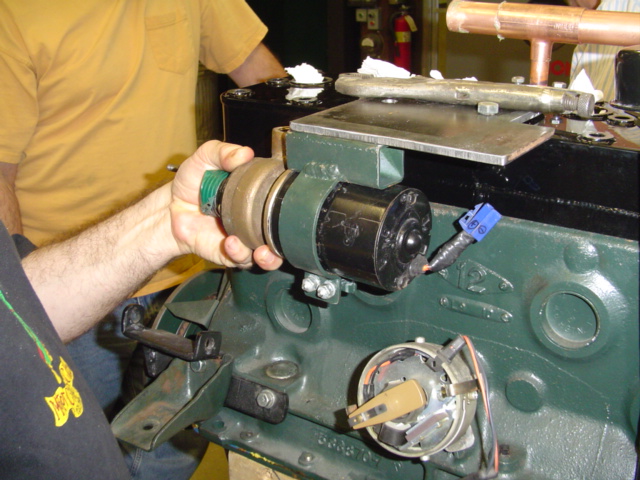
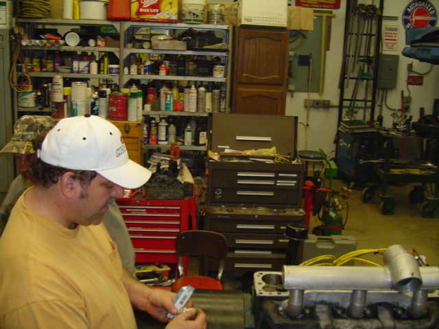
We'll mount the electric water pump next to the head but the inlet will be below the top of the radiator. Last year it was mounted low and on the other side of the engine.
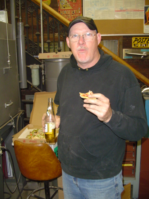
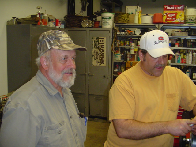
Joe is careful to point out that there's always time for beer and pizza.
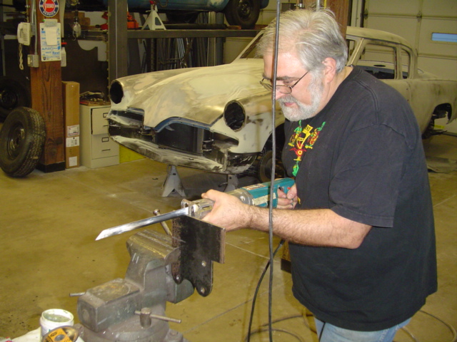
Here Greg notches the mounting plate to accomdate the water pump.
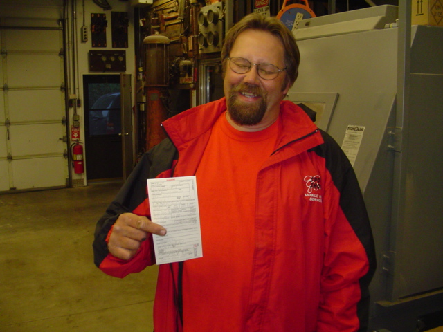
This guy, who will remain nameless to minimize his shame, heard about our project at a Studebaker meet and came up in his tricked out roadster to see what all the fuss was about. He got hassled by 'The Man' right out in front for doing 50 in a 30 or some such nonsense. That'll learn ya to keep in on the salt.
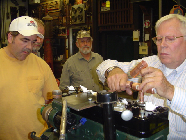
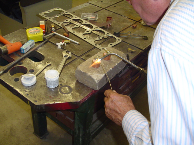
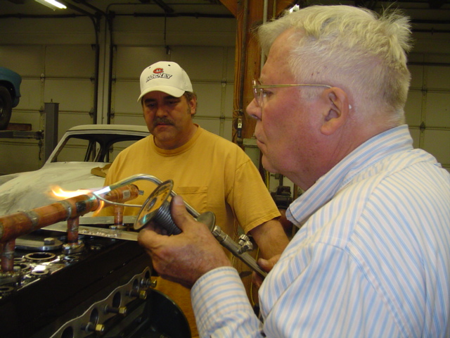
Mike S. shows us which end of the torch to use when sweating pipes to create the cooling system: 1, 2, 3, 4.